
All Products

Triplett offers professional analog multimeter models designed for accurate electrical testing across HVAC, industrial, automotive, and commercial applications. These analog volt ohm meter instruments are engineered to measure voltage, current, and resistance with precision while helping technicians quickly identify faults in electrical circuits and electronic systems.
Our analog VOM meter collection includes compact, portable, and rugged testing devices available in multiple configurations for field service and bench testing environments. Designed with high-sensitivity pointer movement and durable construction, these analog tester instruments provide reliable readings and smooth needle response for monitoring fluctuating electrical signals and unstable circuits.
Commonly known as the “Trusty Workhorses” of the electronics testing industry, analog multimeters use a precision needle display to indicate measurements in volts, ohms, and amperes. Unlike many digital meters, an analog voltage meter allows users to visually track changing electrical conditions in real time, making these tools ideal for troubleshooting motors, transformers, HVAC systems, automotive circuits, industrial equipment, and electrical control systems.
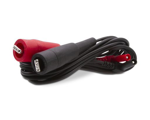
Replacement Lead assembly, right angle CATEGORY: RAILROAD TEST SETS
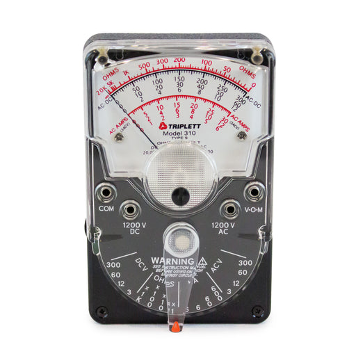
The Triplett Model 310 is a hand-sized analog multimeter with all of the versatility and performance of larger, more expensive bench-size models. R...
View full details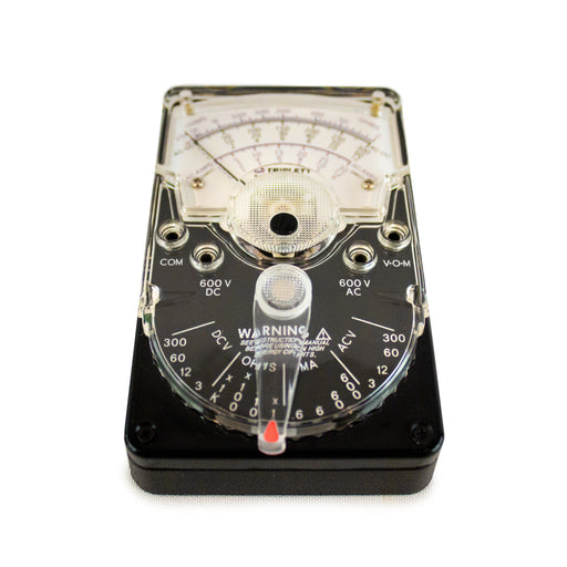

The Triplett Model 310-C is a hand-sized analog multimeter with all of the versatility and performance of larger, more expensive bench-size models....
View full details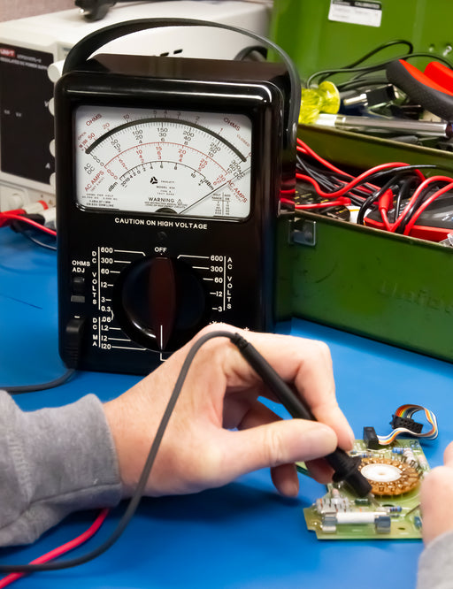
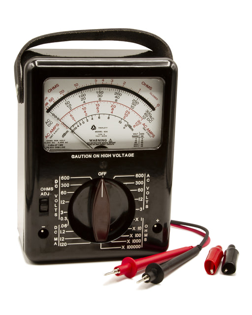
Triplett Model 630 is a compact, rugged, analog multimeter. It has been designed to make fast, accurate measurements on all types of electrical and...
View full details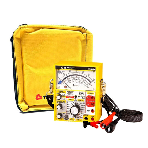
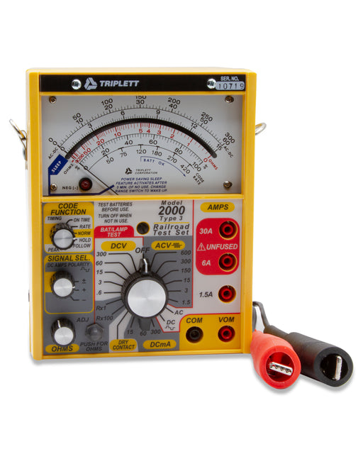
The 2000 Series Railroad Testers are designed to perform standard maintenance tasks (using Volts, Ohms, and Amps measurements) as well as specializ...
View full detailsReplacement Padded case for 2000 series railroad testers. Dimensions: 8" x 7.25" x 5" CATEGORY: RAILROAD TEST SETS
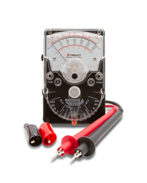
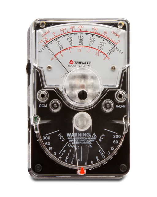
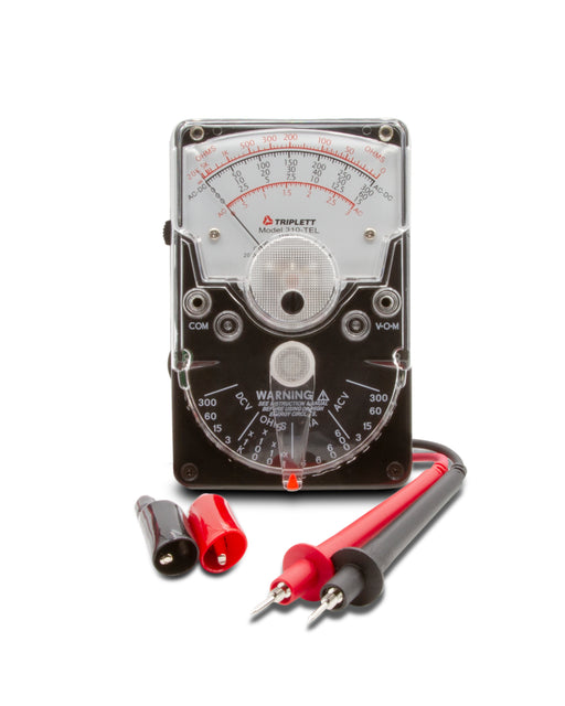
The Triplett Model 310-TEL is a hand-sized analog multimeter with all of the versatility and performance of larger, more expensive bench-size model...
View full detailsKnow More About Triplett Analog VOM Meters
The DC and AC analog voltmeter is that AC voltmeter that measures the root mean square (RMS) value of the voltage (AC). Against this, the DC voltmeter measures the peak DC voltage. Another key difference lies in its working principle.
Follow the below-given steps to use analog volt meter.
You can read an analog VOM meter using the following steps.
An analog VOM (volt-ohm-milliammeter) is a versatile measurement tool with a range of applications in electronics, electrical, and automotive fields. Some common applications include:
An analog tester, also known as an analog multimeter or VOM (volt-ohm-milliammeter), is a versatile electronic instrument used for measuring various electrical quantities in a circuits such as current, voltage, resistance, signal power, and frequency. These devices are widely used to identify and rectify problems in electrical circuits.
Yes, AC voltmeter can be used to measure DC. Electrodynamo meter and moving iron type instruments are generally used for measuring the current. Both these instruments offer the RMS value of AC, which equals to the corresponding DC. If a DC current source is connected to the AC voltmeter, then it would give the appropriate reading.
Analog DC voltmeters are generally available in three ranges - 0-250V, 0-50V, and 0-10V. A user must understand the right display scale before taking the measurements. For instance, if the pointer reads 3V on the 0-10V scale, which is configured for measuring 0-1000V then this reading must be interpreted as 300V.
Both these multimeters measure the changes in voltage; however, the method is different. Also, while digital meters have a display screen to see the values, analog meters have a dial and a pointer. To measure the voltage, analog meters use moving-coil galvanometers which have a suspended coil in a magnetic field. Analog meters are cheaper than digital multimeters because, they do require power supply aide from test source unlike their digital counterparts. While analog meters are durable, the conventional ones may cause confusion in readings. Hence, it is advisable to opt for analog meters with a certain level of accuracy and clarity in readings. Triplett offers analog meters with added features such as AC/DC voltage measurement in a wide range and the scales are clearly defined which increases the accuracy of readings.
Voltage is basically the potential difference between the given two points in a circuit. Here are the steps to measure voltage using an analog multimeter.
While analog meters are perceived to be less accurate compared to digital meters, their accuracy levels can be increased owing to the additional features such as AC/DC voltage measurement up to 1200V, 18 or more such different ranges, fused resistance ranges, and so on. With all these features and more, our handy and portable models of analog meters are as accurate as bench-size ones or digital ones. Most of these models offer accuracy and precision as they have 20,000 ohms per volts DC sensitivity and 5,000 ohms per volt AC and beyond.
Yes, most of our analog meters can measure continuity as they can measure resistance. These multimeters have an Ohm symbol on them. To get these settings right, you need to set the probes in contact with each other and turn the dial such that the pointer tilts towards the extreme right.
Generally, most analog meters comprise scale, pointer, zero-ohm adjustment knob, adjustment screw, ports, testing probes, and range selector knob. Our analog multimeters also come with test leads, alligator clips, a 12V A23, and 1.5V size N batteries.
If a circuit or a particular power carrying line shows a drop in power level or voltage, an analog meter can measure the same. This applies for batteries as well.
The analog tester or voltmeter works on the principle of Ohm’s Law, which highlights the relationship between different electrical parameters. One equation states P=IE, where P stands for power, I for current, and E for voltage. This equation can be easily understood in terms of voltage, resistance, and current. The current is a result of voltage divided by resistance, or resistance is the result of voltage x current.
In an analog tester or voltmeter, the current is passed through a moving coil that lies between two magnets. This moving coil moves along with a permanent magnet on the application of voltage. The voltmeter is connected to the device under test (DUT). The resistor of known value is connected in series to the measurement probes. When the voltage is applied through the coil, a magnetic field is produced, and it produces the pointer deflection. This deflection is directly proportional to the voltage applied to the moving coil. The pointer oscillates for some time, and the reading can be taken when the oscillation stops. If you are using a DC voltmeter, you will observe the polarity signs on it. The positive side of this voltmeter will be connected to the highest point of potential and the negative to the lowest side to achieve deflection. If you are using an AC voltmeter, you need not worry about the signs of polarity, and can directly connect it. A high voltage voltmeter is produced by connecting it with a resistor.
Contact us to get recommendations for choosing the best analog meter for your applications. Also, have a look at our Digital Multimeter DMM and Clamp-on Meters.
To set the analog voltmeter to zero, it is important to use the zero adjustment knob or screw on it. This way you can get accurate measurements, even if no voltage is applied to it.
Yes, analog voltmeters can be used to measure high voltage because they come in different voltage ranges, out of which some of them are designed to measure high voltages. However, you must focus on their accuracy and safety in case of extremely high voltages.
To measure different parameters, you need to follow certain steps that are as follows:
The resistance measurement relies on a tiny current provided by the multimeter’s internal battery, so the battery needs to be functioning properly. The circuit being tested needs to be turned off, to avoid inaccurate measurements or harm to the meter. Handle the device with dry hands.
It is possible to test diodes with certain analog multimeters thanks to their diode check feature. While a multimeter can check for certain junction resistances in transistors, a more specialized tester would be needed for a complete study.
Patch cable is a specific type of network cable used for short-distance connections within a LAN, typically with RJ45 connectors on both ends. On the other hand, network cable is a more general term used to describe any cable used in networking applications such as Ethernet cables (patch cables) coaxial cables, and fiber optic cables.
To protect an analog multimeter, you should:
There are several factors to keep in mind while choosing an analog multimeter for your needs. The below steps will ease the selection for you
Browse More Electrical Test & Measurement Collections
Multimeters & Clamp-On Meters:
| Multimeter Cases | Clamp-On Multimeters | Digital Multimeters |
| Railroad VOM Test Sets | Voltage & Current Dataloggers | Magnetic Field Testers |
| AC Voltage Detector | Continuity Testers | Test Leads |
Electrical Accessories:
| GFCI Receptacle Testers | AC Line Splitters | Electrical Hand Tools |
| Non-Contact Voltage Detection Pens | Circuit Breaker Tracers |
Megohm & Resistance Testers:
| Megohmmeters - Insulation Testers | Earth Ground Resistance Testers |
Live Wire Circuit Testers:
| Live Wire Tone & Probe Kit |
Specialty:
| Power Supplies | Motor & Phase Rotation Testers |
